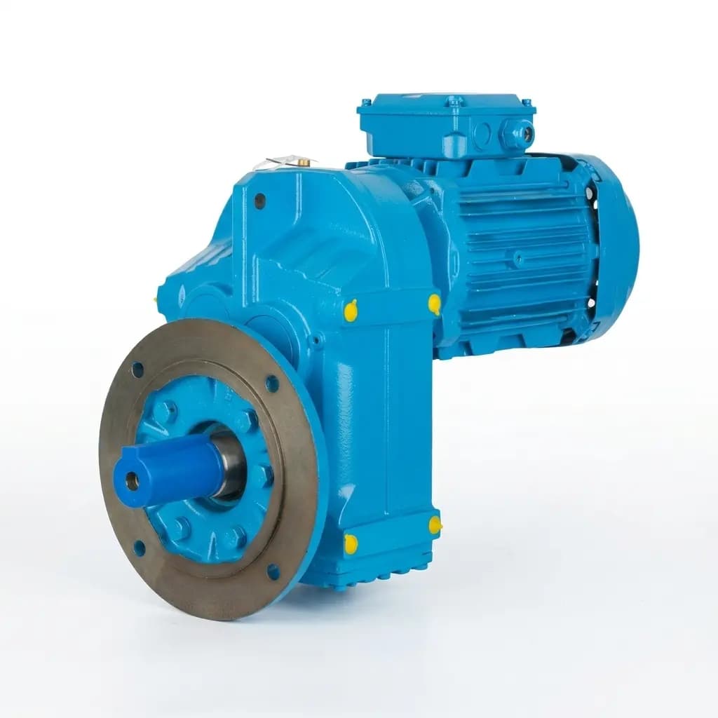
Controlling Backlash in Precision Actuator Gearboxes: DIN/AGMA Standards, Center Distance, and Thermal Drift
How gear quality grades (DIN/AGMA), center distance machining tolerances, and thermal expansion combine to determine actuator positioning accuracy.
"Backlash" is the clearance between mating gear teeth. In standard power transmission, a small amount is necessary to prevent gear jamming. However, in precision robotics, CNC indexers, and aerospace rotary actuators, excessive backlash destroys positional accuracy.
A servo motor cannot accurately hold a position if the gearbox attached to it has 15 arc-minutes of mechanical slop.
1. What is Backlash, Physically?
When the driver reverses direction, the output shaft does not move until this gap closes. In a 100:1 planetary gearbox with 15 arc-min of backlash, the output shaft has a dead zone of approximately ±0.14°. For a robotic arm with a 500mm reach, that translates to ±1.2mm of tip positioning error.
2. Gear Quality Standards: DIN vs. AGMA
The foundation of backlash control is the geometric accuracy of the gear teeth themselves.
| Standard | Equivalent | Process | Profile Error | Backlash Class | Cost Multiplier |
|---|---|---|---|---|---|
| DIN 10 | AGMA 7 | Gear Hobbing (rough) | >18 μm | >20 arc-min | 1.0x |
| DIN 8 | AGMA 9 | Hobbing (precision) | 10-14 μm | 10-15 arc-min | 1.5x |
| DIN 7 | AGMA 10 | Hobbing + Shaving | 7-10 μm | 5-10 arc-min | 2.0x |
| DIN 6 | AGMA 11 | Profile Grinding | 5-7 μm | 3-5 arc-min | 3.5x |
| DIN 5 | AGMA 12 | CNC Gear Grinding | 3-5 μm | Under 3 arc-min | 5.0x |
Moving from DIN 7 hobbed gear to DIN 5 ground gear increases component cost by 5x. Grinding requires prior heat treatment (HRC 58-62) and secondary hard-turning, which adds heat treat furnace time and CNC grinding operations to the routing.
3. Center Distance Tolerance in the Housing
Even DIN 5 precision ground gears will have massive backlash if the housing is machined incorrectly. Housing accuracy is a DFM problem as much as a quality problem.
The distance between the two gear shaft centers is called the Center Distance (a). Its tolerance directly controls the tooth mesh depth.
The Machining Constraint: To achieve under 3 arc-min of backlash, the center distance in the aluminum housing must be held to ±0.010 mm (10 microns).
| Center Distance Error | Effect on Backlash | Effect on System |
|---|---|---|
| ±0.005 mm | Negligible increase | Ideal for DIN 5 ground gears |
| ±0.010 mm | +1 to 2 arc-min | Acceptable for most servo systems |
| ±0.030 mm | +5 to 8 arc-min | Precision destroyed. Positioning error > 0.5° |
| ±0.050 mm | +10 to 15 arc-min | Gears may bind under load or run with severe noise |
DFM Tip: Both bearing bores must be bored in a single CNC setup (without unclamping). Flipping the part introduces fixture stack-up error that can exceed 0.030mm.
4. The Thermal Expansion Trap
Aluminum expands at roughly twice the rate of steel. This destroys many precision actuator designs at operating temperature.
| Material | CTE (μm/m·K) | Expansion at ΔT 60°C (100mm span) |
|---|---|---|
| 6061-T6 Aluminum (Housing) | 23.6 | +0.142mm |
| 4140 Steel (Gears) | 11.5 | +0.069mm |
| Differential | 12.1 | +0.073mm |
At room temperature (20°C), the backlash is a perfect 2 arc-min. Under heavy load, the gearbox temperature rises to 80°C (ΔT = 60°C). The aluminum housing expands 0.142mm across its center distance span, while the steel gears expand only 0.069mm.
Result: The center distance grows by an additional 0.073mm, and backlash spikes from 2 arc-min to approximately 8 arc-min at operating temperature.
Engineering Solutions:
- Material Matching: Use cast iron or steel housings for aerospace-grade actuators, matching the gear CTE.
- Pre-loaded Split Gears: Dual pinion or spring-loaded split gear mechanisms dynamically absorb the thermal gap.
- Thermal Simulation: Model the worst-case ΔT in FEA before finalizing the center distance tolerance. We break down alloy-specific thermal conductivity numbers in our thermal dissipation guide.
5. Specifying Backlash in Your RFQ
Do not write "low backlash." Use measurable metrics:
Gear Quality
All spur/helical gears to meet or exceed DIN 6 (AGMA 11). Process: Case hardened to HRC 58-62, profile ground.
Housing Tolerance
Bearing bore true position for center distance: ±0.010mm. Both bores must be machined in a single CNC setup.
Assembly Backlash Test
Total lost motion at output shaft must not exceed 5 arc-minutes when reversing direction under 50Nm load at 25°C.
Inspection Method
Measure backlash using a calibrated dial indicator at the output flange. Report peak-to-peak reading over 3 reversals.
Frequently Asked Questions
Author

Categories
More Posts
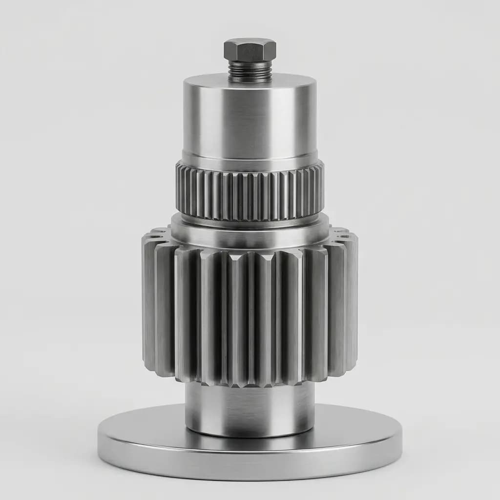
Dimensional Inspection for OEM Actuator Parts: CMM, Profilometers, and First Article Approval
A buyer's guide to First Article Inspection (FAI), CMM measurements, surface roughness (Ra/Rz), and material traceability for outsourced actuator components.
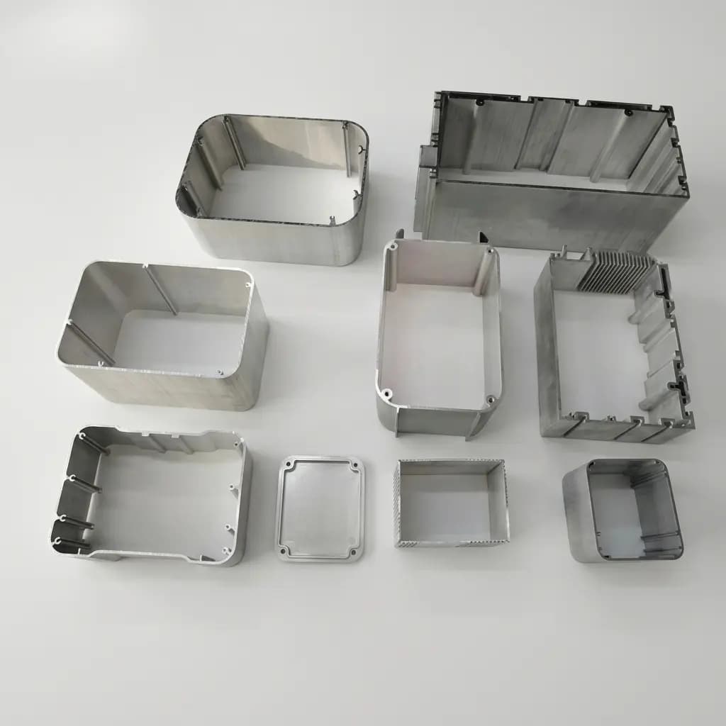
Sourcing Actuator Components for Liquid Hydrogen (LH2): Machining Tolerances & Embrittlement
A procurement guide to LH2 actuator machining tolerances, thermal contraction, surface finish, and embrittlement controls for qualifying cryogenic CNC suppliers.
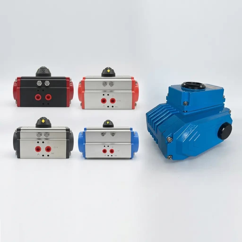
PFAS-Free Actuator Machining: 2026 Compliance, Alternative Seals, and Tighter Surface Finishes
PFAS-free actuator machining guide for 2026 procurement: seal material trade-offs, shaft Ra targets, tolerance shifts, inspection checks, and RFQ actions.